Saeed Norouztamar
Saeed Norouztamar
Abstract:
Kourosh Khalaj Monfared
Abstract:
Ashkan Raki
Abstract:
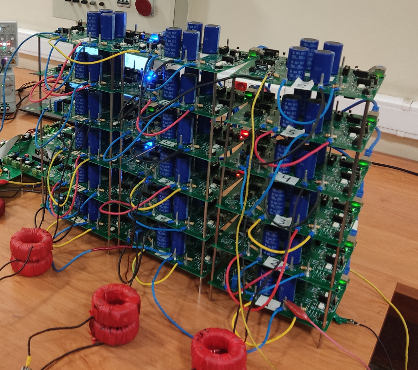
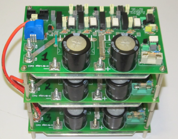
Due to the harmonic characteristics and better power quality, multilevel converters have been utilized in widespread industrial applications such as medium voltage (MV) drives and renewable energy systems. One of the most widely used multilevel converters is the Cascaded H-Bridge (CHB) multilevel converter. The possibility of faults increases since a large number of semiconductor switches are used in these converters. Therefore, to ensure the continued operation of the converter in a faulty condition and prevent the propagation of the fault, it is necessary to utilize a strategy for the continued operation of the converter. In this thesis, a new approach is proposed for the CHB multilevel inverter (MLI) under the faulty situation, when cells with failure switches are bypassed. In the post-fault operation, a common-mode voltage (CMV) is injected into the neutral point of the converter to generate maximum attainable line-to-line voltages. This CMV leads to inequality in the active power of the CHB legs. Hence, the active power of the cells can exceed its nominal power when the fundamental component of CMV (FCMV) is very low. In addition, active power returns from one of the inverter phases to the DC-side when the inverter feeds a low power factor (PF) load. This power flow back increases the DC-link voltage. By increasing the DC-link voltage, the semiconductor devices and the DC-link capacitors of the cell are subjected to severe voltage stress, and the possibility of fault propagation increases. The proposed strategy determines three regions for FCMV, non-overload and non-returnable power. By intersecting mentioned regions, a safe work area is obtained. Therefore, the injection of a minimum FCMV located in the obtained area guarantees the safe operation of the inverter under faulty conditions. The effectiveness of the presented fault-tolerant method is validated using simulation and experimental results obtained from two three-phase 7-level and 5-level laboratory prototype.
Narges Moeini
Abstract:
Nowadays, due to the challenges emerged by fossil fuels, the usage of renewable energy, such as solar, wind, etc. has become increasingly significant. Because most places of the world have access to sunlight, photovoltaic systems have been considered. The goal of this technology is to harvest as much energy as possible from solar panels by tracking their maximum power point, injecting high-quality current into the grid, and increasing a photovoltaic system’s overall efficiency. The classical control methods cannot function properly in the case of severe grid or DC link disturbances. To answer this challenge, time domain models in the form of state equations have been employed in this thesis, and the Hamiltonian model of the system has been derived. To achieve the aforementioned control objectives, two control loops have been used. The first loop is in charge of adjusting the solar array’s output voltage to the desired value in order to assure system performance at the photovoltaic array’s maximum power point. The second loop’s job is to monitor the current injected into the grid to make sure it’s in phase with the grid voltage. The extracted model of system and the IDA-PBC control method have been used to control the grid current in the rotating dq frame. To assess the system’s dynamic and static performance, five different scenarios have been presented, each of which confirms the system’s ability to maintain stability and reach the desired operating point. To ensure the system’s proper operation, experimental tests comparable to Simulation scenarios have been provided.
Mehdi Abbasi
Abstract:
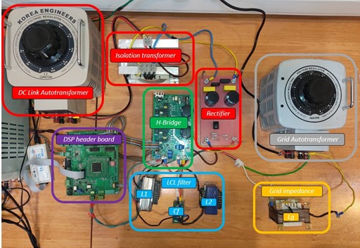
In this thesis, the stability of grid-connected inverters has been investigated and improved. One of the most challenging issues with regard to grid-connected inverters is their operation in a weak grid, which may cause voltage and current instability at the point of common coupling (PCC). A weak grid defines as a grid in which the short circuit ratio is low or the ratio of reactance to path resistance is high. Thus, how to control the converters is vitally important to maintain the stability of the grid. Therefore, grid impedance plays a key role in destabilizing inverters connected to the grid. In order to address the aforementioned problem, two methods are presented in this thesis to increase the stability margin of inverters in weak grids. Both presented methods are based on applying virtual impedance to the control loop, which increases the stability margin. Their difference, however, is in the method the value of virtual impedance is calculated. In the first method, the virtual impedance value is calculated by using the adaptive control of the reference model, and in the second method, the virtual impedance value is generated based on an appropriate algorithmic definition. The first proposed method has no dependency on the number of inverters, while the second method can be used for two parallel inverters. The former method has not been used for grid-connected inverters with LCL filter along with proportional-resonant controller in the literature. Similarly, the latter method has not been implemented on parallel grid-connected inverters in order to enhance their stability. Evaluation and analysis of the stability is also done based on the impedance method and changing the position of the poles of the closed loop system. Finally, the accuracy of the proposed methods is evaluated through simulation. In addition, the first proposed method is practically tested and evaluated by an experimental setup.
Mohammad Sajjad Enayati
Abstract:
Nowadays, due to the increase in the demand of electrical energy and the consequent increase in the price of energy, it is obvious that solutions should be provided to use this energy as optimally as possible. Therefore, in high power applications, the use of new technologies with high efficiency along with appropriate control methods are needed in order to reduce losses and improve power quality. The aim of this project is to use a new switching sequence in space vector modulation in order to reduce switching losses as much as possible and improve distortion. Total harmonics in bridge inverters are series. Providing such a switching sequence is possible due to the presence of repeated modes of the switching vector in multi-level inverters. The accuracy of this method is verified by implementing it in the simulation environment of MATLAB software and laboratory hardware. Keywords: Total Harmonic Distortion, Sequential Bridge Inverter, Switching Loss, Space Vector Modulation
Seyyed Ali Nawabi
Abstract:
Today, permanent magnet brushless machines are widely used in industry and home use due to simple control, high power, very high efficiency and high reliability. Knowing the position of the rotor is necessary to control these machines. The position of the rotor is determined from physical sensors such as the Hall effect and encoders. The disadvantages of using these sensors are their price, the need for repairs, and the increase in engine size. Hall effect sensors do not work well at high speeds due to low accuracy, and heat causes errors in the signal of these sensors. Errors in the installation of Hall effect sensors while building the car and the effect of noise on Hall effect signals are all disadvantages of Hall effect sensors. These disadvantages cause an error in detecting the rotor position, which ultimately causes an increase in torque ripple. In this research, a new method for controlling these machines without using Hall effect sensors and improving their torque is presented. This method is based on the gradient of passive phase counter-motive force and power supply current. Using the slope of the passive phase counter-motive force, the speed and position of the rotor are estimated. The difference between the actual speed and the estimated speed is compensated by the upstream controller of the power supply current. The upstream controller of the power supply current is an adaptive proportional controller. In addition to compensating for the speed difference, this upstream controller reduces the torque ripple by delaying the switching. Knowing the machine parameters is necessary to apply the upstream controller coefficients and slope measurement. The proportional coefficient of the source current controller changes with the change of the current range. Among the advantages of this method compared to other methods based on the anti-motive force of the car, we can mention the engine working in a wide range of speed, easy implementation, working in engine overload conditions. The presented practical and simulation results show the correct performance of this method.
Iman Aghabali
Abstract:
Today, with the expansion of the need for high energy levels in various applications, the use of multi-level converters has increased significantly. Among the various structures of multi-level converters, the modular multi-level converter is one of the most suitable topologies due to its advantages such as modularity, output voltage with low harmonic distortion, no need for a large filter at the output, and the use of a DC link instead of several links. It has been converted for medium power and high power applications. In addition to all the advantages of the modular multi-level converter, the use of multiple semiconductor devices in the structure of this converter increases the probability of a fault occurring, which causes the converter to malfunction. Modular multi-level converters are often used in applications where the slightest interruption in the converter’s operation can cause numerous financial losses. Therefore, after the occurrence of a fault, the converter cannot be removed from the network for a short period of time. For this purpose, a suitable retrofitting method should be considered to control the converter after the fault occurs, so that the performance of the converter can be maintained and returned to normal even after the fault occurs. In this research, at first, the structure of the modular converter in fault-free working conditions and fault-occurring conditions has been investigated, and then a hardware-software integration method has been introduced, which enables the converter to work in fault-occurring conditions with simpler hardware. provides The proposed method is based on the redundancy property of the converter and the ability to move a number of converter cells between different arms, by which the lost levels of the converter can be reproduced after the fault event. In the following, the proposed method is simulated and finally its correctness is confirmed by practical implementation.
Kamal Zaeri
Abstract:
A static frequency converter is used to start energy converters that do not have a starting torque. This converter is one of its key components, and in this thesis, its design and implementation method is presented for domestic production. This reactor is examined from two points of view, magnetic and thermal, and in the magnetic part, a method for implementing the air gap is presented in a distributed manner. Examining the simulation results shows that the only way to build this reactor in a way that replaces the one used in the industrial example is to use the same method of implementing the distributed air gap. There is no experience in building a power reactor with this design in the country. The designed reactor is examined thermally and it is proved by mathematical analysis and simulation in the finite element software that after a certain number of consecutive start-ups, the winding temperature reaches the limit that is limited by the insulation.
Ali Ramezani
Abstract:
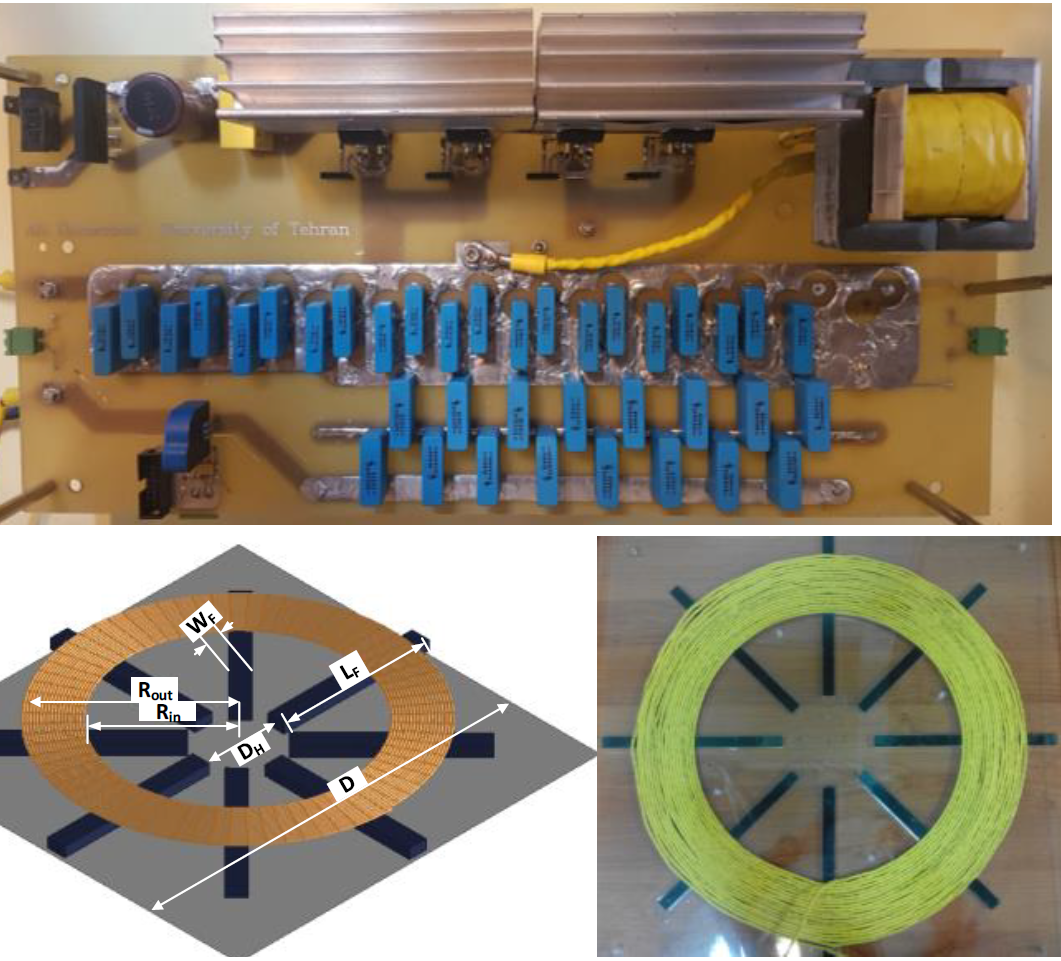
Wireless power transfer is an attractive solution compared to traditional methods for charging batteries and transferring power to electric vehicles. Due to the presence of an inherent isolation in wireless power transmission, it shows higher reliability. A wireless power transmission assembly with magnetic coupling, in order to achieve high efficiency, must have a magnetic structure with a high magnetic coupling coefficient and a high winding quality coefficient. In this thesis, it is shown that for the winding design of this set, in addition to the previous two cases, the sensitivity of the coupling coefficient of the magnetic structure to the changes in the location of the magnetic plates should be low. Then, by introducing the factors that influence the magnetic coupling coefficient and their sensitivity, the optimal design process for this set is introduced based on finite element analysis. In this thesis, the appropriate structure of the resonant converter is selected for use in the power transmission system for charging electric vehicles in stationary mode. With the help of defining an optimization problem, it is designed according to goals and constraints. The results obtained from this optimization are evaluated with traditional methods of comparison and its superiority in the studied indicators. Also, to detect the presence of the secondary in the working circuit, a separate control method is proposed for this power transmission set. Keywords: wireless power transmission converter, magnetic coupling, resonant converter, optimization.
Massoud Noushk
Abstract:
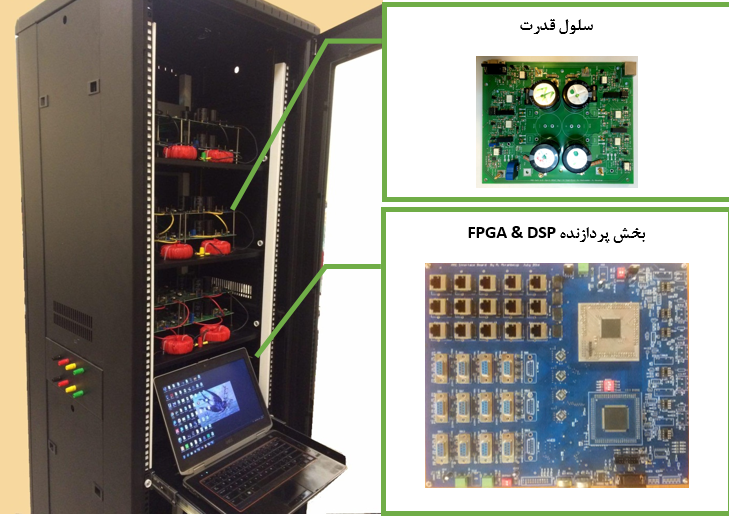
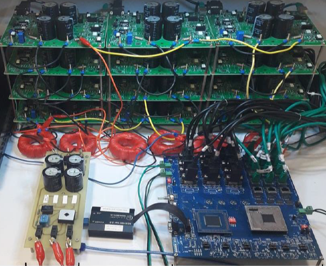
One of the challenges of modular multi-level converters in the drive of variable speed medium voltage drives is the increase of capacitor voltage ripple at speeds lower than the rated speed, which disrupts the drive performance. This issue also arises in the startup of the drives, so that the startup of the drive faces a problem. In this project, a method based on trapezoidal wave injection to phase voltage and rotating current is presented; In this way, by reducing the voltage ripple, there is a significant improvement in the performance of the converter at low frequencies in terms of capacitor voltage ripple, injected rotating current and the harmonic quality of the output current compared to the previous methods. By simulating the presented method and existing methods in the Simulink MATLAB environment and comparing the results, the superiority of the presented method is determined. In order to confirm the simulation results, a three-phase laboratory sample has been designed and built, in which 4 half-bridge cells are used in each leg. In order to increase the processing speed, DSP and FPGA processors have been used and the challenges of its implementation have been solved. Finally, using practical results, the improvement of the proposed method is confirmed compared to other methods.
Alireza Hadizadeh
Abstract:
Today, modular multi-level converters with unique features such as modular structure to produce desired voltage levels, very high efficiency, very good harmonic performance, reduction of the dimensions of the output filter and output waveform with excellent quality, have gained wide acceptance in the industry and energy systems. have brought Since power electronic converters act as an energy interface between the input and output parts, the stable operation of this converter depends on its correct control. With the increasing use of this structure in high power applications and the use of many semiconductor elements, the calculation of losses is of particular importance. In this report, a method for calculating losses based on the equations governing the converter in steady state is presented. Also, by injecting a certain second harmonic wave into the reference wave, the losses of the converter have been reduced and consequently the efficiency of the converter has been improved. Also, a method based on genetic optimization algorithm has been presented to control the converter as well as to reduce the circulating current and voltage ripple of the capacitor of the cells. The presented method controls the converter by injecting a specific second harmonic wave into the reference wave and ensures the converter’s performance in optimal conditions. In addition to that, the stages of designing and manufacturing a three-phase modular multilevel converter with 8 cells in each phase are presented and the results of simulation and implementation are also presented.
Abdul Rahman Sajjadi
Abstract:
Due to the importance of improving power quality in power systems, the use of parallel compensators has been considered. In this thesis, a new method for balancing the DC link capacitor voltage of the cells in the series bridge converter used in the parallel compensator is presented. The modulation used to control the keys in the mentioned converter is of the type of elimination of certain harmonics (SHE), which due to the low frequency of this modulation, the switching loss in the converter is minimized and leads to an increase in its efficiency. Also, by making the voltage of the cells asymmetric in a desired ratio, the voltage steps in the output waveform are increased and the harmonic distortion of the voltage is reduced. The use of degrees of freedom in the mentioned modulation to keep the voltage of the cells balanced and not using classical controllers has made the dynamic response of the system to the reactive power step to be improved to a great extent. In order to check the effectiveness of the proposed method, the simulation of the parallel compensator based on the sequential bridge has been done in the PSCAD software environment based on a three-phase inverter with two cells in each phase. Also, by simulating the desired system under the changes of network parameters (passenger and filter resistance), the sensitivity of this method has been checked from this point of view.
Mohsen Kamali Rad
Abstract:
In this thesis, a converter with a high frequency AC connection is introduced to transfer the power of the solar array to the three-phase network. The arrangement used for this purpose has a basic structure of reversing buck boost, which has been modified for three-phase application. A new keying method is provided for the mentioned structure, which provides soft keying conditions. In this converter, the power transfer is not dependent on the difference between the voltage level of the solar array and the grid voltage, while in conventional photovoltaic converters, an input layer is needed in order to raise the voltage of the solar array to transfer power to the grid. The structure and control algorithm of this converter is simplified compared to the converter of the same category. The absence of common mode flow is one of the other advantages of this converter. Because this converter is used in photovoltaic applications, the problem of tracking the maximum power point is of great importance, and a method for doing this is proposed according to the behavior of the presented converter. Also, in this converter, it is possible to create galvanic isolation between the solar array and the three-phase grid, using a high frequency transformer. In order to check the correctness of the converter and the proposed keying method, this converter was first simulated and then implemented in a practical way, the results of which are favorable. At the end, suggestions for studying to improve the performance of the proposed converter as well as the performance of this converter in specific conditions have been presented in future research.
Ramin Rahimi
Abstract:
Among renewable energy sources, solar energy is of great importance due to its easy access and low operating cost. Today, most of the solar energy systems are connected to the grid. Photovoltaic inverters connected to the old grid are isolated from the grid; Galvanic isolation in these inverters is done by a high frequency or line frequency transformer. Structures with high-frequency transformers include several stages of power conversion, which increase the price of the system and reduce the efficiency. The low frequency transformer is also large and heavy. Therefore, it makes the system bulky and difficult to install. In order to increase the efficiency and reduce the volume and price, the transformer is removed, which leads to the creation of leakage current from the path of the parasitic capacitor between the solar modules and the ground. The amount of parasitic capacitor depends on various factors such as module type, module frame structure and weather conditions. The leakage current is mounted on the injected current to the network and increases its harmonic distortion. Also, this leakage current increases losses and electromagnetic interference. The amount of leakage current depends on the structure of the inverter and its switching method. According to the standard VDE 0126-1-1, the effective value of the leakage current should be less than 300 mA. In the articles, the issue of leakage current in photovoltaic inverters connected to the grid without a transformer has been investigated, and solutions have been proposed to reduce this current. In this thesis, two new structures are proposed to reduce the leakage current in three-phase photovoltaic inverters connected to the grid without a transformer. Then, in order to validate the proposed structures, the results of the simulation and implementation of the action are presented. Both simulation results and practical implementation show that the proposed structures have good performance in terms of leakage current and THD of injected current into the network.

Shafi Rezaei
Abstract:
Bipolar DC microgrids were introduced in 2010 as a solution for systems that require a microgrid with high reliability and efficiency. One of the most important challenges in this type of DC microgrid is the existence of the central voltage balancer, which is used to balance the voltages of the two output terminals of the bipolar DC microgrid. For this purpose, new bipolar converters are presented to answer this challenge. In this thesis, by presenting a new two-way bipolar converter, the voltage control of the two terminals of the bipolar microgrid and the energy transfer between the two terminals of the DC microgrid and the input source will be done. The voltage balancing operation can be done in a distributed manner, in which case the proposed converter connects the energy storages to the microgrid. The converter can also be used as a central converter in the output stage of the AC/DC interface converter. In each of the output terminals of the bipolar DC microgrid, it is possible to consume or produce energy, and according to the status of each terminal, the energy exchange between the input source and the DC microgrid will be different. When both output terminals of the DC microgrid consume energy, the input source supplies the energy consumption of the two output terminals of the microgrid. In cases where the energy production in one output terminal of the DC microgrid is less than the energy consumption in the other output terminal of the DC microgrid, the proposed converter supplies part of the energy consumed in an output terminal by transferring energy from the terminal that produces energy, and the rest of the energy from The input source is provided that this type of operation causes less energy to be received from the input source than before. Also, when both output terminals of the DC microgrid have energy production, or the energy production in one of the DC microgrid terminals is greater than the energy consumption in the other terminal, the energy produced from the DC microgrid is transferred to the input source. Next, with the help of small signal analysis, converter conversion functions are extracted and suitable voltage controllers are designed based on them. The proposed structure and voltage control loops are checked by performing multiple simulations in Simulink MATLAB environment. In addition, the accuracy of theoretical results is also checked with the help of laboratory results.
Massoud Shahab Aldini Parisi
Abstract:
Today, with the increase in the number of sensitive consumers, the importance of the issue of power quality has increased. One of the main problems of power quality is lack of voltage, for which dynamic voltage compensator is one of the most common solutions. The dynamic voltage compensator is placed in series in the network and by continuously measuring the voltage on the network side, it detects the errors caused by the lack of voltage and fixes it by injecting the voltage. Because the voltage compensation process may be accompanied by active power injection, the ability of a compensator, especially to compensate for voltage shortages with greater depth and for a longer period of time, depends on the amount of energy stored in its DC link. To solve this problem, you can use a number of compensators that are connected to different feeders, while all these compensators have a common DC link. This structure of compensators is called inter-line voltage dynamic compensator. The inter-line voltage dynamic compensator has the ability to transfer active and reactive power between independent feeders through a common DC link and thus help the compensation function. The basic challenge in front of the introduced voltage compensators is that their performance and efficiency are highly dependent on the load power factor. For example, these compensators are in no way able to compensate for the lack of voltages that occurred on feeders with ohmic loads. In order to overcome this problem, in this thesis, a method is presented that, in addition to solving the challenge, can significantly increase the compensation capacity under lower power factors. One of the main parts of the inter-line voltage dynamic compensator are converters. Multi-level converters are a good choice for use in inter-line voltage dynamic compensators due to their many advantages over conventional two-level converters. Among the various configurations of multilevel converters, the sequential bridge configuration is the best configuration used for the compensator. For this reason, in this thesis, for the first time, multilevel converters of sequential bridge have been used in the structure of inter-line voltage dynamic compensator. On the other hand, multilevel converters need more complicated controllers than traditional converters. Voltage control of DC link capacitors in multi-level series bridge converters is one of the most important challenges related to this type of structure. For this purpose, it has been tried to provide a simple and new control method for controlling the voltage of the DC link capacitors of these converters in this thesis.
Alireza Ramyar
Abstract:
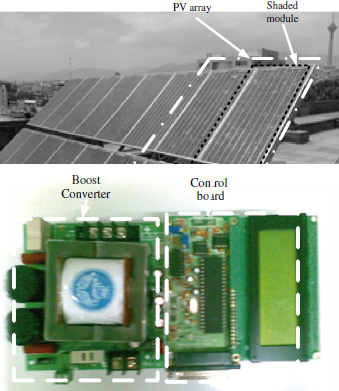
This thesis has proposed a new control strategy for tracking the maximum power point of solar arrays. Unlike the usual methods of tracking the maximum power point of solar arrays, this method is able to work well even in the conditions of partial shadow phenomenon. In partial shade conditions, the power-voltage characteristic of solar arrays is multi-peaked, unlike uniform radiation conditions. In case of wrong tracking of the maximum power point of the arrays, it is possible that a significant part of the array’s productive power will be lost. Therefore, it is very important to correctly track the main peak of the power-voltage characteristic. The proposed strategy is based on the current-voltage characteristics of solar arrays. Based on this, the proposed strategy has modified the conventional hill climbing method to be suitable for working in partial shade conditions. This strategy is very simple and has an acceptable speed. To study the proper performance of the proposed method, several simulations have been done. Also, to provide practical results, the boost converter was designed and built and the correctness of the proposed method was confirmed in practice. Keywords: maximum power point tracking, photovoltaic array, partial shade, power-voltage characteristic, current-voltage characteristic
Abbas Kayani Harchgani
Abstract:
The modular multilevel converter, MMC (Modular Multilevel Converter), has been welcomed by engineers and researchers in the last few years due to some characteristics and advantages compared to other multilevel converters, and a lot of research is being done in this field. Balancing and controlling the voltage in this converter is a fundamental element, so that the correct operation of MMC is not possible without this important realization. In this thesis, most of the presented methods for controlling the voltage in the MMC converter are divided and analyzed into two parts: balancing and controlling the average voltage of the cells. Voltage generation at the output of this converter with two types of modulation ?+N and ?+N? Surface is possible. Voltage generation ?+N? level, although it reduces the amount of harmonics and, as a result, the quality of the voltage is better, but due to the lack of stability in the number of light cells in each leg in this modulation, the current of the arms is distorted and the circulating current inside the dc loop of the converter increases. Therefore, a method to reduce the circulating current produced in this modulation by applying corrections on the MMC converter is presented in this report. In this report, a single-phase SHE modulation is also introduced for multi-level converters, which, of course, is due to the fluctuating voltage of the cells from one side and being dependent These fluctuations are converted into working point, the harmonic spectrum in the real state is different from the ideal state. Also, the stages of designing and building a system laboratory sample including a single-phase MMC converter with four cells in each leg and the results of implementations related to cell voltage balancing and SHE modulation proposed on it will also be presented and analyzed. Keywords: modular multilevel converter, MMC, voltage balancing, ?+N and ?+N? modulation Surface, SHE single-phase modulation

Hoshang Salimian Rizi
Abstract:
In recent years, due to the need for higher powers, the use of series bridge converters has been expanded. Due to the large number of semiconductor switches used in these converters, the possibility of errors also increases in them. In order to ensure the continued operation of the converter and to prevent the increase of damage, it is very important to detect and locate the fault, as well as the resistant performance of the converter against fault conditions. Sequential bridge converters have many redundant states to produce the output voltage, which makes fault location difficult. In this thesis, a method for detecting and locating the open circuit fault in series bridge converters is proposed. The proposed method for fault detection and location compares the reference voltage commanded by the control system with the value of the output voltage of the converter phase in the time domain and detects it in the event of a fault. To measure the output voltage and current direction, one voltage sensor and one current sensor are used in each phase, which is the least number possible. A method for switching has been proposed, which, in addition to producing the desired voltage at the output, ensures fault location in the shortest possible time, independent of the modulation method and the size of the modulation coefficient. The effectiveness of the proposed method has been confirmed by simulation and laboratory results. A method is also proposed to continue the operation of the converter after the occurrence of an error by producing the highest possible output voltage similar to the normal state. The proposed method adds an auxiliary module to the converter. The proposed method has a lower cost and equal or greater production power than similar methods by adding hardware. By implementing the method in the simulation environment and laboratory hardware, its accuracy has been confirmed. Keywords: Sequential bridge converters, fault detection, open circuit fault, fault tolerant operation
Erfan Qadri
Abstract:
In today’s world, at any place and at any time, there is a possibility of sudden cardiac arrest for every person. In the absence of immediate first aid, the chance of survival of a person with this condition is greatly reduced. Automatic external electroshock device is a portable and automatic device that can treat sudden cardiac arrest by applying electric shock when necessary. By receiving and analyzing the vital signal of the injured person’s heart, this device detects the person’s need for an electric shock, and if this shock is needed, the high voltage part of this device applies the appropriate electric shock to the injured person’s body. The shock section of the AED device converts the device’s battery voltage into a high voltage suitable for electric shock and stores it in a capacitor or capacitor bank. The stored energy is then applied to the body of the person in cardiac arrest with a certain voltage waveform, which increases the probability of a successful electric shock. In this research, the high voltage part of the AED device is designed and implemented by circuit elements available in the country’s market. Due to the limitation of the nominal voltage of the capacitor and electric switches available in the market, a cascade structure has been used to implement this part of the device. To increase the probability of shock success, in this thesis, the voltage waveform is selected according to the impedance of the injured person’s body. Also, by reducing the capacity of the storage capacitor, the energy stored at a constant voltage value decreases. By doing this, the energy consumption of the battery is reduced and the battery life of the device is increased. In other words, in this case, for a fixed battery, the number of shocks that can be applied to the device increases. Keywords: automatic external electroshock, sudden cardiac arrest, vital heart signal, monophasic, biphasic, flyback converter
Behnam Noori
Abstract:
With the increase in the share of production from wind energy, the blackout of wind farms can lead to the instability of the grid voltage in the affected areas. On the other hand, wind power plants are more sensitive to power grid fluctuations and disturbances than fossil fuel power plants. In order to make the effect of wind power injection more bearable on the stability and power quality of the grid, a series of new regulations titled “Grid Connection Requirements” have been set by the power transmission line operators. The ability to withstand voltage shortage is one of the most important functional requirements of wind farms, which is required for the stable and reliable operation of the power grid. Due to the increasing importance of the behavior of wind turbines against faults, it is necessary to create a suitable laboratory environment for testing generators in order to check the performance of these turbines and avoid damages caused by their unfavorable performance in the network. The used industrial and research structures are slow, stepwise and expensive, and the need for fast, accurate and practical structures in real scale is still felt. In this thesis, a new structure is proposed for the test system of wind turbines, so that it can be used to apply accurate, fast voltage reduction according to the voltage reduction test standards. The desired control method for the test system is the predictive control method. In this thesis, a proposed method is presented to solve the shortcomings of the model-based predictive control method, such as the volume of calculations and high switching frequency. The proposed structure of the wind turbine test system is designed and simulated. In this system, the predictive control method of the model and the proposed control method of simulation and its results are presented. By analyzing the simulation results, the system structure and the proposed control method are completed. In the following, the proposed test system has been implemented at the laboratory level with a power of 10 kW. Also, the test results of network connection requirements based on different standards are presented. Keywords: grid connection requirements, undervoltage fault tolerance, wind turbine test, wind turbine with bi-feed generator, undervoltage simulator, model-based predictive control method
Massoud Shamali Shahreza
Abstract:
In this thesis, a new method for controlling a wind turbine equipped with a bi-fed induction generator in the unbalanced network voltage mode is presented. The proposed control system is based on the vector control method and is designed in such a way that it can use the main controllers of the system that are used in normal mode, even in the condition of unbalanced network voltage. The behavior of the control system and the bi-fed induction generator in unbalanced voltage conditions has been shown, and since the vector control of the bi-fed induction generator is based on the power equations of the rotor-side converter and the grid-side converter, in the proposed method, the equations The power of both converters in unbalanced voltage conditions has been extracted and used in the implementation of the control system. The active and reactive power in the stator and grid-side converter in unbalanced voltage conditions can be separated into two separate parts: the product of the positive sequence components and the product of the negative sequence components. In the proposed method, by considering the approximation and ignoring the negative sequence components, it can be seen that the power equations in unbalanced voltage conditions are similar to the power equations in normal operation conditions and it can be obtained from the current reference of the converters. In normal operation conditions, it is also used to control converters in unbalanced voltage conditions. With this, the need to determine a new current reference for power control in two converters in unbalanced voltage conditions is eliminated, and the transition from normal to unbalanced voltage conditions is done with greater speed and better dynamics. The use of approximation in power equations causes a mismatch between the reference value and the actual power value in two converters, which can be ignored in the low voltage imbalance percentage. For example, in a 10% voltage imbalance, this discrepancy is less than one percent. The negative sequence components of the two converters are also used to compensate for torque fluctuations, active and reactive network power and capacitor link voltage. The simulation of the proposed method has been done using Simulink MATLAB software on a 2 MW wind power generation system to show the accuracy of the proposed method and its proper control in unbalanced voltage conditions.
Amin Torkahvand
Abstract:
One of the most essential information for the system operator in order to monitor the power system is the dynamic parameters of the system. These parameters are either unavailable or, if available, change over time. Updating and estimating parameters for system models has always been important for reliable operation of the network. Also, the realism of the available model is very important in terms of security, reliability and economic exploitation of the system. The validity of the power system model is important in the sense that it is possible to predict the response of the system to various events and errors through simulation. On the other hand, with the erosion and changes of the power system, the system model parameters change. Therefore, the availability of available model parameters increases the accuracy of the predicted response. On the other hand, the introduction of phasor measurement equipment (PMU) in power systems and the increase in its growing applications have created a revolution in network monitoring. Therefore, the use of these equipments to update and estimate power system parameters has attracted the attention of many researchers. In this project, with the aim of estimating the inertia of the system, a method for estimating the inertia of system generators using the data of power and frequency changes measured by phasor measurement units is presented in the face of large errors such as generator outage. Then it deals with parameter estimation for power system dynamic models using overall system data after large faults. In the following, a method for estimating the internal reactance of the classic generator model (second order) is presented, and the electromechanical parameters of the classic generator model are estimated with the methods of least squares regression and Kalman filter. These parameters include inertia constant, damping coefficient and mechanical power of the generator. It is worth noting that to estimate the parameters of the classical model of the generator, the bus terminal data of the generator after the small signal errors obtained by the phasor measurement units are used. Keywords: parameter estimation, phasor measurement unit, inertial constant, damping coefficient, oscillation equation.
Mohammad Reza Miran Beigi
Abstract:
Due to the ever-increasing share of solar energy in the production of electrical energy and the continuous reduction in the price of solar modules in recent years, the technical issues related to solar arrays have been highly considered. Maintaining the stability of solar systems and increasing the efficiency of solar converters are among the most important technical issues in this field. Traditional methods for connecting the multi-level inverter to the grid are not able to maintain the stability of the system in the condition of the heterogeneity of the modules. In this thesis, the combined modulation method, which has previously shown an acceptable performance in converging the voltage of capacitors in rectifiers, has been investigated for a multi-level photovoltaic inverter connected to the grid. Two methods have been proposed to implement the combined modulation, the first method is based on the two-loop control of voltage and current, and the second method is based on calculating the power slope. The above method is able to maintain the stability of the system and receive the maximum possible power from the arrays in a wide range of heterogeneity of solar arrays connected to bridges. It is also possible to reduce the effective switching frequency and increase efficiency with this modulation method. To check the dynamic and static performance of the system, two scenarios for the voltage control algorithm and three scenarios for the power slope control algorithm are presented in the simulation section, which confirms the proper performance of the system. Experimental tests are also presented in this regard, similar to simulation scenarios, to demonstrate the performance of the system in the real world. Keywords: inverter, solar cell, combined modulation, power slope control, voltage control
Muhammad Najjar
Abstract:
The growth of electricity production and consumption and the increase in the number of branches in the power system have caused the level of short-circuit current to increase in some parts of the network, which will cause severe damage in the power system if the network structure is not modified. Therefore, equipment is needed to bring the level of short circuit current at these points to the desired values. On the other hand, the problem of power flow control and better use of transmission lines is very important. The interphase power controller (IPC) is one of the new members of the family of FACTS devices, which has capabilities such as reducing the level of short circuit current, absorbing and producing reactive power, controlling power flow and also separating two networks. The thesis is designed based on the relationships of an IPC sample in the d-q device, which uses a voltage source converter in its structure, two control systems in which only active power is controlled in one and active and reactive power in the other. The simulation done in MATLAB software is based on the parameters of one of the lines in Tehran’s power grid, which is based on the results of load distribution. Finally, considering that no laboratory sample of this equipment has been built so far, a single-phase sample on a laboratory scale was built based on successive H-bridge converters that have common capacitive links to compare the simulation results with practical results. The obtained results should be compared.
Meraj Nowrozi
Abstract:
In this thesis, the control of dual-feed induction generator is studied and simulated in the grid-independent mode. Controlling the stator voltage range and frequency is one of the upcoming challenges in grid-independent mode, which will be completely in charge of the dual-fed induction generator. On the other hand, the power demanded by the load must be well answered. In this regard, in this thesis, the functional principles of wind turbines are presented first, the types of wind turbines are introduced along with the advantages and disadvantages of each one, and finally, due to the special features of the dual-feed induction generator, the basis of studies and simulations Placed. Then the relationships and equations expressing the behavior of the turbine and the relationships governing the control function of the double feeding induction generator are analyzed in a basic way. In the following, the control systems are introduced in such a way that they answer the basic needs in the independent mode of the network. The correct operation of the designed control systems is verified in the Matlab/Simulink software environment. In the simulations, the performance of the wind turbine in the grid-independent mode is checked for changes in local load power, changes in rotor speed, the presence of unbalanced loads, and the use of three-level converters. The simulations and its results show the appropriate performance of the selected control systems and solve the upcoming challenges in the field of wind turbine control in grid-independent mode. Finally, to work in real conditions, in order to operate the wind turbine in a grid-independent mode, an energy management method has been proposed to make more use of the wind turbine in these conditions, which has not been investigated from this point of view in various sources. In this method, the greatest possible kinetic energy is always stored in the inertia of the turbine and causes more exploitation of the wind turbine. The results of this energy management method are analyzed at the end.
Mehraz Amini
Abstract:
In recent years, solar energy has been considered as one of the clean and renewable energy sources. The most important discussion in the field of solar energy is the lower price, high efficiency and appropriate quality of power injected into the grid. Although the multilevel series bridge inverter is a good choice for grid-connected photovoltaic applications (due to having separate dc buses), the control issues in it have not been fully resolved. One of the most important challenges is related to the low stability margin of the series bridge inverter in asymmetric radiation conditions. In this thesis, a modified maximum power point search method is investigated in the seven-level series bridge converter connected to the grid. In the proposed method, in addition to following the maximum power point of the solar arrays separately in the symmetrical mode, in the asymmetrical mode, by moving the working point of the modules and using the modulation coefficient of the bridges as a degree of freedom, correct and stable power injection continues. . It is necessary to explain that in current sequential methods, power injection should be stopped in radiation asymmetric conditions and more harmonic currents should be prevented from being injected into the network. In the end, the correctness of the proposed method is confirmed through numerous simulations as well as laboratory results.
Mahmoud Nouri
Abstract:
400 Hz inverters are widely used for providing electricity to airplanes in the aviation industry, as well as in military equipment and shipping industries. Controlling the current amplitude and frequency of the output voltage, especially in the conditions of asymmetric and non-linear loads, is the main goal of the control system in the inverter. Many control schemes in the field of 50/60 Hz inverters have been reported in the articles. Few of these methods can be directly applied to 400 Hz inverters. Because the main cycle period of recent inverters is small and equal to 2.5 milliseconds. The delay caused by a sampling period at this frequency is 8 times larger than 50 Hz systems, and this time delay increases proportionally with the reduction of switching and sampling frequency in high power applications. In this thesis, the double-loop control method is used to control the 400 Hz inverter. The control is designed in the abc stationary device. Therefore, in order to achieve zero steady state error in tracking the sinusoidal reference voltage, a resonant controller has been used in the outer loop. Dominant harmonic controllers are used in a parallel structure with the main harmonic controller. In order to avoid phase delay and reduce the bandwidth, a proportional controller has been used in the inner loop of the flow. The controller coefficients of the inner and outer loops are designed by a combined digital method in the domain of discrete time and continuous time. In order to isolate the control system from the load flow disturbance input and improve the dynamic response of the system, the feed block has been added to the two-loop control structure. Also, in order to implement it safely against the noise of the pre-eating block, a soft derivative which is optimally designed for the frequency of 400 Hz has been used. Several simulations have been performed to verify the efficiency of the control system, which indicates the optimal performance of the transient and permanent state of the system. In the end, the practical results obtained from a 20 kVA industrial laboratory sample prove the theoretical estimates of this thesis. Keywords: 400 Hz inverter, double-loop control, digital control, hybrid digital design
Youssef Nishaburi
Abstract:
In this thesis, considering the increasing importance of power quality in power networks, a new method for reactive power compensator control based on three-phase sequential full-bridge converter, based on mode feedback control with integral detector design, is presented. The sequential full bridge converter used in the proposed compensator is switched by the sinusoidal phase shift width modulation method and does not require separate dc sources in the dc links of the cells and is directly connected to the medium voltage line without the need for a coupling transformer. will be The proposed method locates the special structure of the system in such a way that stability and dynamic response are provided. The proposed method has good resistance to the changes of compensator parameters (including resistance and filter inductor). In the proposed algorithm for balancing the dc link capacitors of the full-bridge series converter, the charge of the dc link capacitors is balanced under conditions where the cells have different losses, and in the constant working conditions of the system, the voltage fluctuations in the dc link capacitors are A suitable value is limited, which is effective in improving the quality of the injected flow to the network. The efficiency and correctness of the proposed method have been investigated by using simulation on the compensator based on a 21-level three-phase full-bridge converter with a rated reactive power of 1.5 MW, and the implementation on a seven-level single-phase full-bridge converter. . In the following, using the introduced mode feedback control method, and with the aim of reducing the converter losses and improving the efficiency of the compensator, a method to apply the algorithm for removing certain harmonics on the parallel compensator based on the full-bridge series converter has been used. Key words: multilevel converter, full-bridge sequential structure, reactive power compensator, balancing algorithm, mode feedback control
Esmail Ebrahimzadeh
Abstract:
Lack of voltage is one of the most common power quality problems that causes a lot of damage to sensitive consumers. The most appropriate compensator for voltage deficiency in terms of economic and efficiency considerations is dynamic voltage recovery (DVR). The control systems that have been introduced so far for compensating voltage shortages have problems such as not compensating unbalanced zero-sequence shortages, too much calculation volume, or low response speed. Considering these disadvantages, in this thesis, a modified control system based on the proposed estimation method and four-leg inverter-based hardware is used. The proposed estimation method, which is an improved least square method, along with the conventional least square method are implemented by DSP and compared with each other. Keying commands are generated using the proposed modulation method, which is easier to implement than other methods. The proposed modulation method and the conventional modulation method in ABC space have been compared using simulation and laboratory results. The effectiveness of the proposed control system has been investigated by simulating the power system of Mazandaran wood and paper factory. These simulations have been carried out under conditions of balanced and unbalanced shortages with linear and non-linear loads. In this thesis, a laboratory DVR was designed and built, and with its help, the correctness of the proposed estimation method, the proposed modulation method and the overall performance of the device in compensating balanced and unbalanced deficiencies have been confirmed.
Amir Hossein Moeini
Abstract:
In this thesis, a new method for controlling active rectifiers is presented. Also, an improved method for applying the modulation method to remove certain harmonics to the active rectifier of the sequential bridge is presented. One of the methods introduced in this thesis is the design of a new control system in order to improve the speed of applying the controller command to the modulation part of the active rectifier. For this purpose, it has been tried to improve the network voltage estimation speed using existing methods. In the following, an improved method for applying low-frequency modulation to remove certain harmonics is presented to the active rectifier of the sequential bridge. By using this method, while keeping the switching frequency of the power switches to a minimum, it is possible to balance accurately and with minimal ripple in the dc links of the active rectifier for the converter. Also, the low-order harmonics in the voltage and current waveform of the rectifier are placed in their desired values. Finally, the efficiency and correctness of the proposed algorithm are checked by computer simulations as well as laboratory implementations on a series bridge rectifier with three cells. Keywords: Multilevel converter, full-bridge sequential structure, active rectifier, elimination of certain harmonics, PSO optimization method.
Mohsen Alinejad
Abstract:
Nowadays, power electronic devices are made in different types and for different applications, among these equipments, multi-level voltage source inverters are one of the most widely used structures. If, for any reason, one of the power switches in these inverters fails, the output waveform will undergo many changes, which may cause serious problems for both the inverter and the load connected to it. Therefore, a method should be provided to guarantee the continuous operation of the multilevel converter after the fault occurs. In this thesis, a new method for the continuous operation of the full-bridge sequential multilevel converter in the condition of fault occurrence is presented, which creates a good combination between the modification of the hardware arrangement and the modification of the inverter switching method. In this method, after the occurrence of an error, using a number of supporting devices, the arrangement of the converter is modified in such a way that the production of symmetrical voltages by the inverter is possible, then by changing the modulation method, the efficiency of the inverter is guaranteed in the event of different errors. Also, in this thesis, a new modulation method is presented, using which the main component of the output voltage is increased and the inverter usage rate of the DC link voltage is improved. This new modulation method is then used to operate under fault conditions in the full-bridge series inverter and improves the efficiency of the inverter. Since the number of output voltage levels decreases after the occurrence of a fault, the use of more DC link voltage leads to a partial compensation of the reduction of the output voltage in the fault condition. In order to confirm the performance of the proposed methods in various error conditions, several simulations have been done in the software environment. Also, the practical implementation of the proposed method on the multi-level full bridge converter has also confirmed the results of the simulation
Abbas Eskandari Qadi
Abstract:
In this thesis, two symmetric and asymmetric sequential full-bridge multilevel converters for use in grid-connected solar systems have been studied and investigated. In the symmetrical structure, the stability margin of the inverter is determined with the help of mathematical relationships. Then, to improve the performance of the symmetrical bridge converter and maintain the modulation index of the cells in the linear working area, two control methods are proposed. In the first solution, by moving the working point of solar arrays in unbalanced atmospheric conditions, the stability of the system is guaranteed. In the second proposed method, to increase the stability margin of the system, a backup battery is used, which can be charged and discharged in a suitable way. In scientific articles, the use of asymmetric sequential multi-level bridge arrangement for solar applications has been given less attention. Therefore, by using the combined modulation method, a new method is introduced to control this structure, which, while receiving the maximum possible power from the solar arrays, increases the quality of the current injected into the network compared to the symmetrical state. The correctness of the proposed methods has been confirmed through simulation in PSCAD software.
Ali al-Naghi Marzooqi
Abstract:
In this thesis, two new control methods are introduced for the full-bridge series converter. Considering the increasing attention to power quality issues in power networks, both proposed methods try to improve power quality. In this research, first, a brief history of active rectifiers is presented, and then, the types of structures of multilevel converters are briefly described. Then, the advantages of the all-bridge rectifier structure are stated and its requirements for proper operation are described. Various methods for controlling and modulating the full bridge rectifier in sequence along with some of its most important applications are described below. Finally, two new methods for controlling the mentioned rectifier are proposed and reviewed. One of the methods introduced in this thesis is a new algorithm for implementing the well-known method of removing certain harmonics on the full bridge rectifier. Then, the efficiency and correctness of the proposed algorithm are checked by computer simulations and also laboratory implementations on the full bridge rectifier with three cells. Another method introduced in this thesis is a new method to control the full-bridge rectifier in series as a parallel compensator for reactive power. Since the proposed method does not require an input current sensor, its implementation reduces the cost of the system and increases its reliability. The efficiency of this method has also been investigated by simulations and implementations. The results obtained from both proposed methods confirm the accuracy and correctness of the proposed methods in meeting the respective objectives.
Alireza Kochaki
Abstract:
In this thesis, a new method for tracking the maximum power point in partial shade conditions is presented. The partial shade that can be caused by the shade of trees, buildings, clouds, etc. causes the power-voltage characteristic of the photovoltaic array to become multi-peaked. In this situation, the usual tracking methods such as the hill climbing method have problems in tracking the main maximum power point. By developing the relations governing the photovoltaic array in partial shade, this thesis has been able to provide an analytical condition for distinguishing partial shade from uniform radiation conditions. Also, based on the relationships obtained, the relationship between the corresponding voltage of the power peaks is obtained, and with its help, the tracking of the maximum power point during the partial shadow event is done more quickly. This method also has good reliability and finds the main maximum power point in different radiation conditions with high speed and accuracy and without confusion (one of the disadvantages of hill climbing methods). Since the tracking algorithm in this thesis has found the ability to work in any radiation conditions with a slight change in the hill climbing method, therefore the algorithm is very simple and therefore it is easy to implement in practice. In order to verify the performance of the proposed method, several simulations have been performed in different radiation conditions in the software environment on a boost converter. Also, using practical tests, the correctness of the algorithm of the maximum power detector has been confirmed.
Reza Teimurfar
Abstract:
In this thesis, the aim is to analyze and design a static energy storage system (installed on the ground) for the subway using supercapacitor. Metro Line 3 of Tehran has been chosen as an example. First, the metro network includes trains, lines, rectifier post and energy storage system. Then, with the help of the mentioned model, the metro network was simulated in PSCAD software and the reproduction flows were analyzed. In order to optimize the components of the energy storage system, using a proposed method and by expanding the voltage and current equations of different points of the network, the regenerative and consumed energy of each station is calculated and a cost function is defined for the entire metro network. For filling and emptying the supercapacitors, a suitable converter has been selected and a control scheme has been proposed for the desired system. Using the MATLAB software optimization toolbox, the mentioned cost function has been minimized and the nominal values of the energy storage system, including the nominal capacity of the capacitor bank and the nominal values of the various components of the converter, have been determined. The metro network along with the proposed system is simulated in PSCAD software. The performance of the proposed system has been evaluated by examining the voltage and current diagrams of various system components and calculating the efficiency of the converter. Finally, by calculating criteria such as energy saving percentage, amount of stored energy, initial investment cost, investment return period and current value of investment, the desired system has been economically analyzed.
Suleiman Galshi Mozirji
Abstract:
Numerous researches and measurements have been done all over the world about power quality, and all these researches show that power quality problems are the cause of great losses to industrial units. For this reason, today there is a lot of effort to increase the quality of power in the network. Lack of voltage is one of the most common power quality problems. One of the most common solutions to compensate the lack of voltage is to use a dynamic voltage compensator. The inverter is one of the main parts of the dynamic voltage compensator. The multilevel inverter is a suitable option for use in the voltage dynamic compensator due to its many advantages over the normal two-level inverter. Among the various arrangements of multilevel converters, the series bridge arrangement is the best arrangement for the multilevel inverter in dynamic voltage compensator. One of the challenges of the multilevel inverters of the series bridge is the voltage control of its dc links. In this thesis, a new control method is presented to control the voltage of dc links of a multi-level series bridge inverter. Also, a new model for estimating the asymmetrical three-phase voltage is introduced, which is able to estimate the main harmonic of the three-phase voltage faster than conventional methods in the unbalanced state and in the presence of high harmonics. The correctness of the performance of the introduced estimation model and voltage controllers is checked by simulation as well as practical results on a laboratory sample.
Mohammad Ali Rezaei
Abstract:
The ever-increasing need for energy, as well as the pollution caused by fossil fuels and the limited nature of these resources, have encouraged people all over the world to replace these resources with renewable resources. The decrease in the cost of new energy, especially photovoltaic energy, and on the other hand, the increasing price of oil, promises to increase the use of this energy source in the near future. The most important debate in the field of solar energy is the cost of energy obtained from cells and the quality of power injected into the grid, which in recent years researchers have tried to improve by using multi-level inverters. The multi-level full bridge (CHB) inverter is the most suitable option for use in photovoltaic applications due to its separate dc buses. Despite the advantages of CHB inverters, their control issues have not been fully investigated in scientific and practical articles and research. One of the most obvious issues is the low stability margin of multilevel inverters in the condition of asymmetric dc inputs. In this thesis, a new control method is presented to control the DC bus voltage of the CHB converter. Based on the extracted mathematical relations and using the power factor of the converter as a degree of freedom, a new control method is presented to improve the stability margin of the CHB converter. The correctness of the proposed strategies is checked using simulation and practical results on a seven-level full-bridge inverter.
Power Electronics and Energy Systems Laboratory was established in 2010 with the aim of training efficient engineers and researchers. In this educational and research environment, specialized fields such as the design of power electronic systems, including all types of power supplies, inverters and rectifiers, high and multi-level power converters, types of high voltage or HV systems, energy conversion systems, etc. are under study and research.

Design: Mahyan